Woah nelly. These new motors are a bit bigger than I expected. I thought I might be able to work with the existing mount on the lathe but it quickly became clear that wasn't going to happen.
Every once in a while I sit back and think about how much more work I'm making for myself. At some point I actually hope to get back to using the machine for making things, instead of making things for the machine.
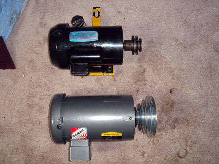
This motor will be driving the lathe:
Baldor CM3554-5
1.5HP / 3 Phase / 1725 RPM
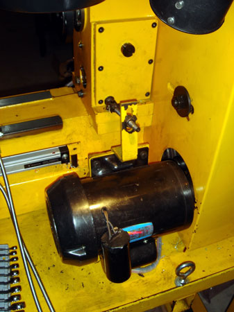
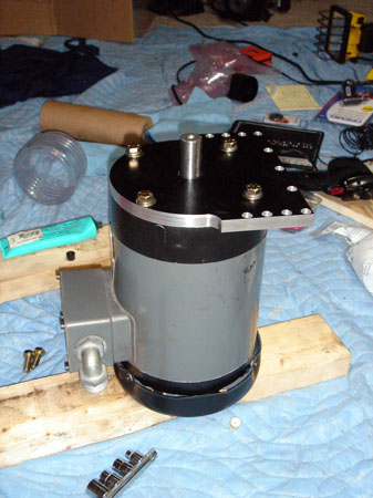
Lathe motor before...
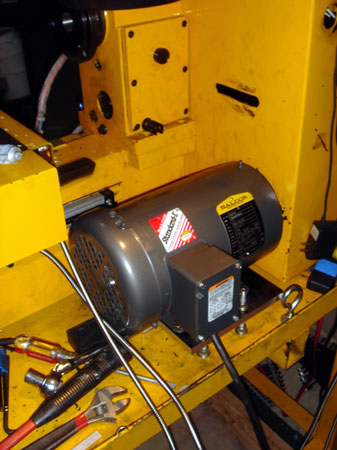
Lathe motor after!
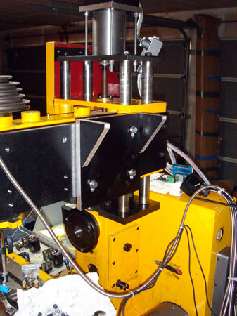
Getting the mill motor mounted was going to be a bit tricky. There is no way to reach two of the mounting bolts when the assembly is bolted up.
The solution was to separate the assembly into two parts. So, I bolted on this section first.
Then the motor was mounted to the other plate.
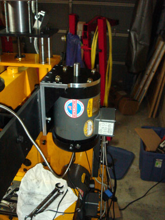
At this point I could just set the motor up on top of the gussets and it would stay in position, so I could get all the screws in, with very little effort expended to hold the motor in the air. Seems to be working so far!
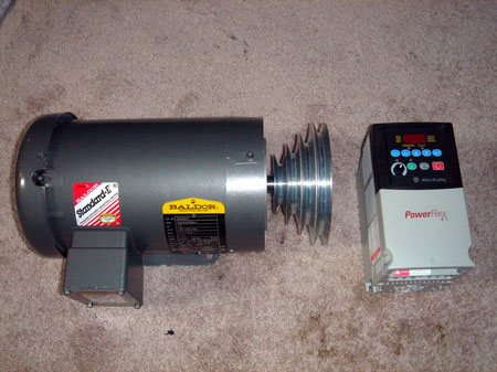
The VFD will be plugged into my dryer outlet so I'd need a VFD capable of converting 120 Single Phase into 220 3 Phase. The Allen Bradley 22A-A8P0N104 seemed like a good choice.
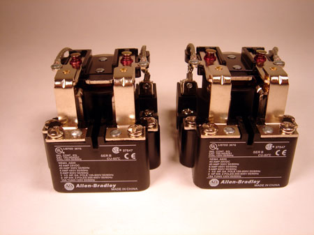
A set of two contactors will let me switch the VFD control between the lathe and mill motors. This means I can use the power feed while running the mill anymore, but that's another story.
I couldn't get a triple pole double throw contactors on short notice, so two DPDT's will have to suffice. This actually gives me an auxiliary contact...for something I might want to hook up...someday.
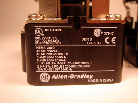
A shot of the specs in case anyone is interested.
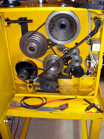
This is really the part I've been dying to do! Rip all that junk out of there.
And, through the power of the internet, it only takes a couple turns of the scroll wheel and viola. I sprayed some dychem remover on a towel and it took all that black gunk right off. Almost looks new.
You can see the finger prints of someone...probably one of the people that assembled the machine, on the rim of the spindle pulley. Kind of cool.
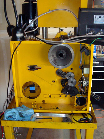
I just couldn't wait to try this out so I set up for a preliminary test.
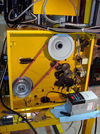
You can't really tell here but she's runnin'! Not perfectly of course. Turns out the step pulleys I bought from MSC are seriously off center. Haven't quite decided what to do about that yet. These things are hard to find.
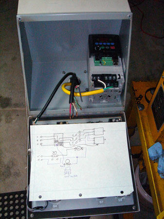
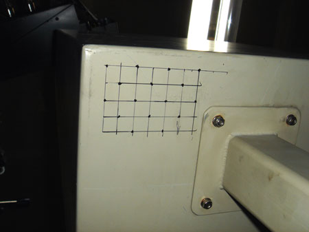
Okay, never tried to wire anything like this before. I drew myself a rudimentary diagram to help me keep track of where I was going.
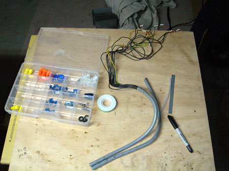
Pulling the cords up through the box was interesting. I tied a bolt on the end of a string and dropped it down the hole in the bottom of the box.
Next I put a magnet on the end of a length of coat hanger wire. There is a hole near the mounting bracket on the horizontal part of the arm for wiring. I ran the magnet down to the elbow, snagged the bolt and pulled the string through.
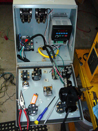
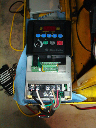
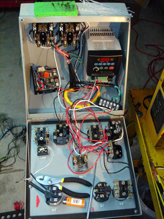
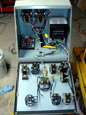
The contactors and the drive are mounted. The board on the left side is my KB Controller for the future X axis power feed. Time to dive in.
Okay, not diving quite yet. I wanted to mention, the VFD has a fan on the bottom, a big heat sink and exhausts out the top. Mounting in an enclose close to the bottom...not recommended.
To allow air intake to the fan I drilled some 1/2" in holes in the bottom and on the top for exhaust. I'm planning to add an actual exhaust fan at some point.
Okay! Now we're diving. It's hard to tell, but I'm trying to keep the AC and DC lines separated.
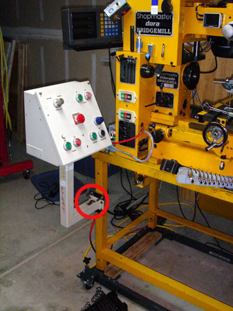
Very exciting, all wired up and the test runs went fine. I'm using a built in relay on the VFD to power the red light on the stop button. I jumpered in from the input terminals on the VFD and set the relay to activate under a "motor running" condition through the setup menu.
I've also configured to run on a "three wire" control button scheme. This gives me start, stop, and reverse on separate buttons. The "two wire" scheme allows for run forward, run reverse and stop.
I ended up using red wire for all of the DC pathways. Not exactly proper but it gets the job done.
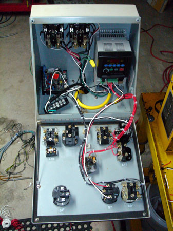
After playing around with the controls for a while the wiring started to bother me. So, I ripped it all out and started over when I realized I could use one of the control cables that came with the surplus box.
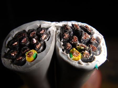
It has 12 leads and I needed 11 to wire all of the DC activated buttons including the potentiometer for the power feed.
Much cleaner and the AC and DC has even better separation with only one cross over. I've heard AC and DC lines in parallel can cause feedback in the VFD. Fired it up again and it still runs!
Right now the VFD is programmed for a 5 second ramp up and a two second stop. One nice thing about this AB unit is that it's equipped with dynamic braking, so you can set it to...bam...stop. Maybe good for threading.
Well, now I just need to get some pulleys that are round and I'll be all set. I'm hoping that's what is causing that speed related noise you hear in the video. So close yet so far! Thanks for tuning in and feel free to email.