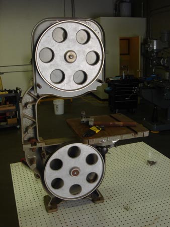
This thing was beat up and I got it for free. It sat outside for about a year, but it was in LA so it didn't really see that much bad weather. It came with what you see here, a stand, and nothing else.
I wasn't very dilligent about taking picures of all the steps.
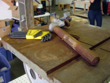
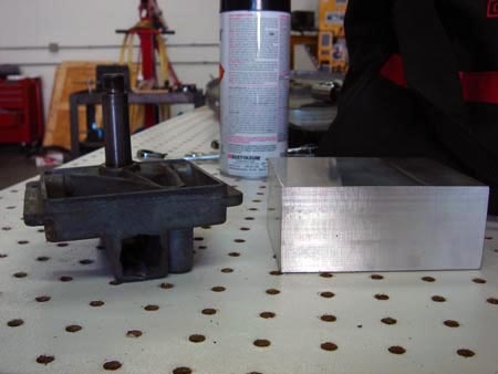
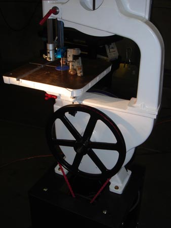
I also failed to do a good job of before and after pics but this is pretty representative of "before." Busted and rusty.
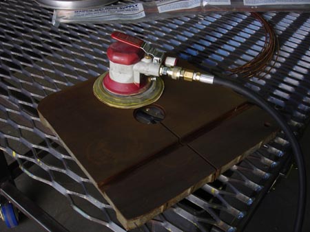
I tore the thing down to parts and went to work lowering any high spots.
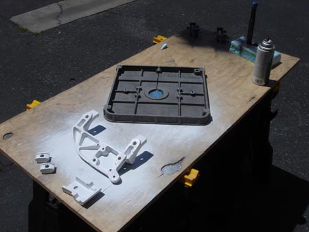
I sand blasted everything that would fit into the cabinet and proceeded to paint. I found some "appliance enamel" spray paint at the local hardware store and bought some black and white.
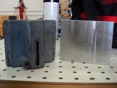
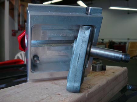
This is the tensioner housing and I discovered a big crack in the casting. Time to reverse engineer!
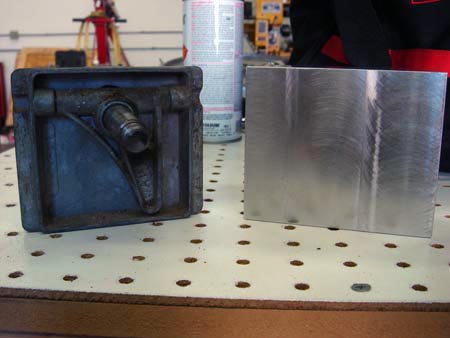

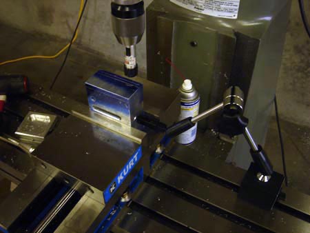
I couldn't live without my 12" height gage and 12x18 surface plate. Well, I could but I'd spend a lot more time fiddling around and not making chips.
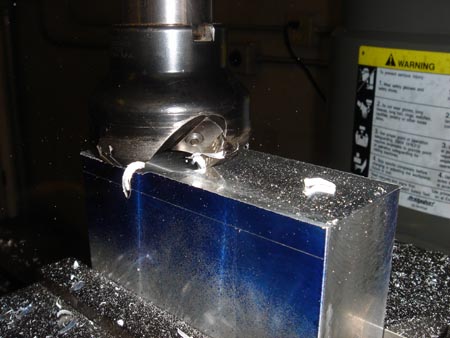
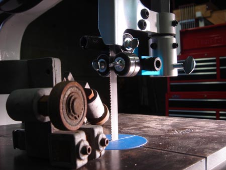
This is a live action shot where the flash stopped the face mill so you can see a rare moment...the birth of an aluminum chip! This is a 2" Kennametal face mill and a Bison R8 arbor that I bought on ebay for about 75 bucks. I'd say it's my most frequently used milling tool...that and the laser.
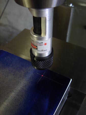
I won't bore you with too many steps here but here is Mr. Laser meeting a couple of scribe lines. I made the laser brighter so you can see it in the picture, but the dot is much smaller when adjusted with the polarizer.
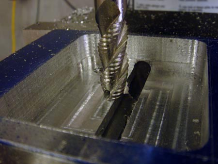
This is hogging out the cavity with a 3 flute roughing endmill. I highly recommend the rougher. I've already bored the length of the block (4 jaw on the lathe) that will accomodate the tension spring.
I'm using my indicator arm as a poor man's work stop. I have a rich man's work stop (made it myself) but this is quick and easy. I need to drill and ream two holes that will carry the dowel pins that form the hinge for the tracking adjustment. When one side is finished I just flip it and put it against the stop...and hope the two holes come out parallel.
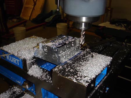
The rougher roughing out the outside profile. Those little granular chips are also super easy to vaccum up and don't clog the hose.
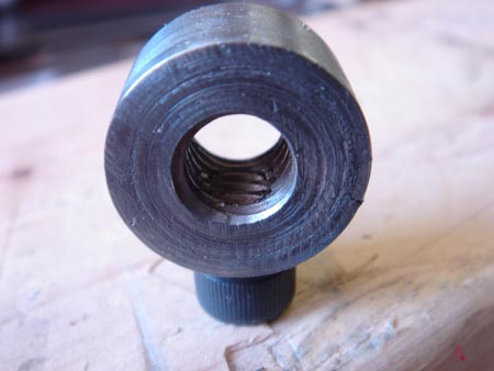
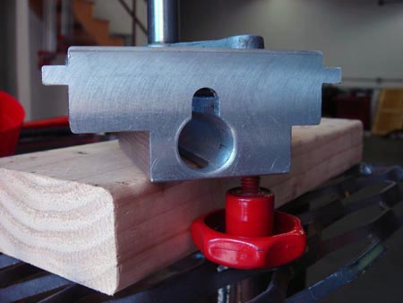
Okay, so before the big reveal, allow me a moment of vanity. The original tensioner used a square nut that prevents the nut from turning in the bore, thus allowing the spring to compress. I didn't have any way to make a square hole, so I came up with this.
I threaded a cap screw into the side and then drilled and tapped the screw and the "nut" at the same time. When the adjuting rod is threaded through, the screw is captured and can not back out. This will be clear(er) in the next shot.
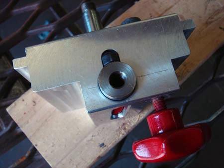
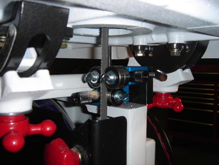
So here we are looking at the bottom of the bracket. The head of the cap screw rides up and down in the groove, preventing my "nut" from turning, allowing tension to be put on the spring. What spring?
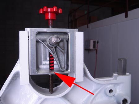
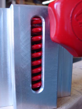
This spring. You can see the "nut" at the very bottom of the braket if you look closely. Now for a few glamour shots...
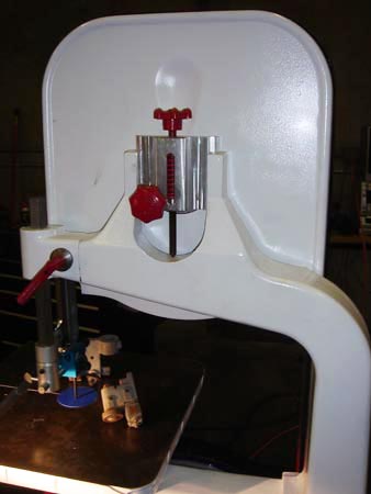
You can see the bolt threaded through the back of the bracket that acts as the tracking adjustment. I re-used the original cast bit that holds the spindle for the top wheel.
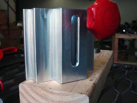
I went ahead and chamfered this slot and corner-rounded everything else because I was feeling fancy.
Whew, so the major work is done. I also replaced this rusted solid piece of junk with a set of (top/bottom) Carter Micro-Adjust ball bearing blade guides. Since the saw was free I felt like I could spend a copule of bucks.
Here is the underside.
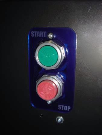
I also bought a huge friggin' bag full of old Allen Bradley buttons off of Ebay. Let's just say I have a lifetime supply and I'm looking for any excuse to use them. How about here?
The blue surround is laser cut acrylic and covers the original switch hole on the base. The two buttons just barrrrely fit.
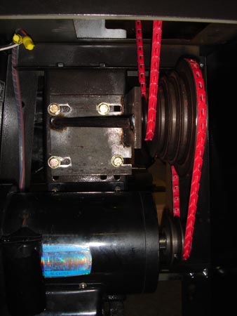
Whe I got the saw it didn't have any drive components at all so I canibalized one of the old motors from the Shoptask and one of the pulleys as well. The pulley is the middle one.
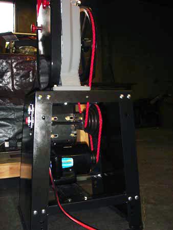
I'm also going to send a shout out to Fenner link belts. They are awesome! How awesome? So awesome I don't have to build in any method to adjust the belt tension because you can do that with the belt itself. Let's take a closer look.
Okay, after all that hard work I got a little lazy and didn't paint the mount.If you are wondering how it's just hovering there, The end of the bearing housing has a stand off and a couple of threaded holes so it is bolted in from the back.
I had to fabricate a bracket to hold the big step pulley from the Shoptask. Just a couple pieces of 1/2" steel plate welded together and reinforced with a 5/8" piece of round bar. Both the motor and the bracket fit into existing mounting slots on the vertical support member.
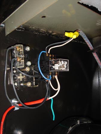
After a bit of head scratching I finally remembered how to wire a holding circuit on the relay. Haven't figured where to mount the ground wire yet since the motor doesn't seem to have a ground?
Here is the big ole' pulley I ordered from McMaster. I made some rough calculations and sized this final pulley to give me about 80 rpm at the shaft. The blade is "about" 7 feel long so that gives me 560 sfm.
It seems high on paper but I find it's about right for any metal that I've tried to cut on it, and I've passed through some pretty hefty steel chunks for a 14" wood bandsaw. The variable pitch bi-metal blade helps.
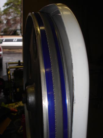
Whew, not done yet. Have to put on a couple of urethane tires...
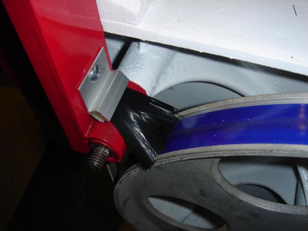
A little brushy thing..
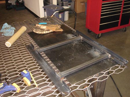
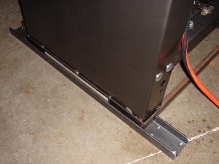
And make a rolling base! Some 2" C-channel and 1" square tube.
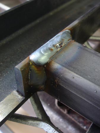
Yep a little MIG action on the Miller 212.
This is hard to explain but it fits nicely.
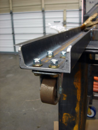
Wheels, wheels are good.
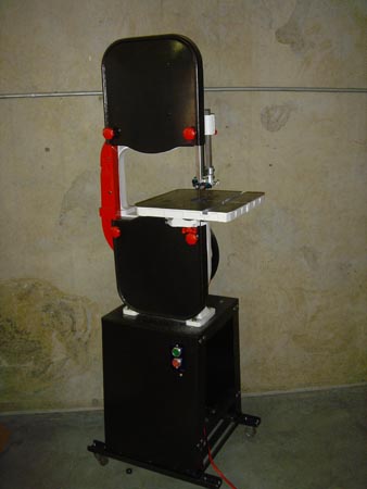
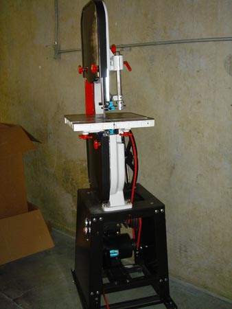
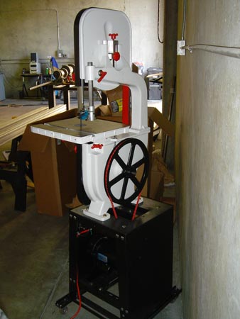
And here she is! From left out in the yard rust bucket to the best 14" bandsaw I've ever seen. The only things I spent money on: blade guides, tires, brushy thing, the actual blade, steel for the mobile base, and a few cans of spray paint.