ST X Axis Power Feed
I actually did this mod a long time ago but forgot to put it up on the site. This is a really great upgrade for those of us without CNC.
The main drawback is there is no way to quickly engage/disengage the power feed to allow easy manual rotation of the feed handle. It rotates, but you have to overcome the gearing in the motor and it take some effort. I just use the power feed to traverse both directions, or I can just loosen the set screw on the drive pulley for full manual mode.
So my strategy was to use the mounting point for the CNC upgrade and also use the timing belt pulley already attached to the lead screw.
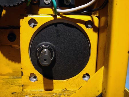
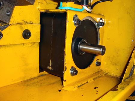
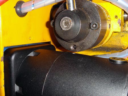
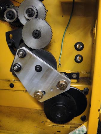
I used a rotary file in a die grinder to turn the holes into slots and got the motor fitted up.
You can see some scrapes on the side of the motor case, near the bottom. The fit was very tight and it took some filing to fit it in there.
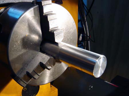
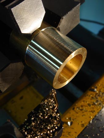
Time to make some idler pulleys. I made the shafts out of 6061.
I made two and each was I tapped 3/8" to accept the mounting bolts.
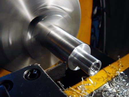
A chunk of delrin will fit over this shoulder and be a hair shorter than the standoff height. .
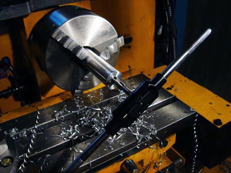
Parting with my modified HSS tool...before I went indexable. If you haven't checked out my HSS parting tool mod you should consider it. Grinding in a bit of top rake and feeding "relatively" aggressive made a HUGE difference in terms of parting performance.
Before the grind parting was a real pain, after, a joy.

To measure the right diameter for the delrin, I just put the stand off into the end of the reamed hole and turned till the OD of the delrin was just a bit oversize compared to the stand off. I made two.
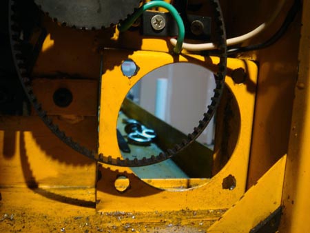
I forgot to take any photos before I mounted it up but here ya go. Timing belt pulley on the motor shaft. The two grade 8 bolt heads (brassy colored) hold the idler pulleys. The mounts are slotted so the pulleys can move around to adjust belt tension.
The three black nuts are existing mounts on the Shoptask.
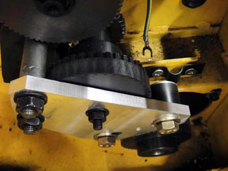
Here you can kind of see the top idler. The timing belt runs in between the two idlers so the smooth surface is running on the delrin.
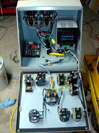
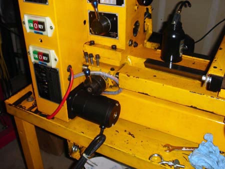
In the bottom left of my control box is a KB DC motor controller that I also found on Ebay. I haven't wired it in this shot since the photo is from my VFD upgrade.
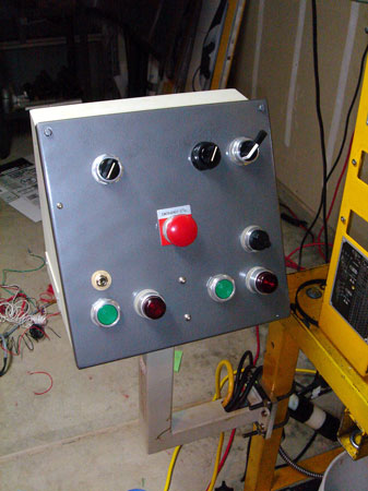
If you split the panel down the middle in to left and right halves...the VFD controls are on the right and the power feed controls are on the left.
The top left knob is the speed control. In the bottom left is the reversing switch and the start stop buttons.
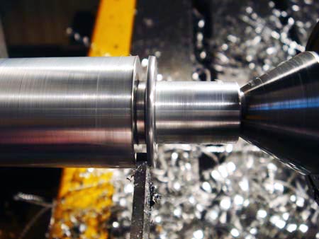
This is a shot of the finish using the power feed.
Not bad eh?